The main computer of the robot will be based on the 6502 CPU which was immensely popular in the late 1970-ies to late 1980-ies and used in many home computers and consumer products. Amazingly this CPU is still being used and produced today almost 50 years after it was first introduced. That makes it easy to get hold of new reliable chips.
The computer will be modular consisting of a mostly passive back plane and all functions of the computer on individual plug-in boards using classic PCB edge connectors. This is both similar to how some old systems were designed, and it gives lots of flexibility and makes development easier. But most importantly: it looks cool and retro.
I’m using Ben Eater’s design and tutorial videos as basis for my design. Both because he has solved any potential issues with timing and because I can reuse his programs for testing the system to get started. If you’re planning onf duplicate this project or building another 6502-based system I highly recommend watching his YouTube videos, and supporting him by buying his complete computer kit.
I’ve so far made preliminary designs of the back plane, CPU board, clock board, LCD display board and two visualization boards for debugging. The PCB routing has been done to resemble auto-routed cards from the 80-ies so they are kind of badly routed on purpose.
Back plane


Main CPU Board


Clock board
The main CPU board has an integrated 1MHz oscillator, but it also has the option to take a clock signal from the back plane. That’s where this board comes in. The external clock board has a selection of different frequencies as well as an adjustable low frequency 555-based oscillator and the option for manual single stepping.


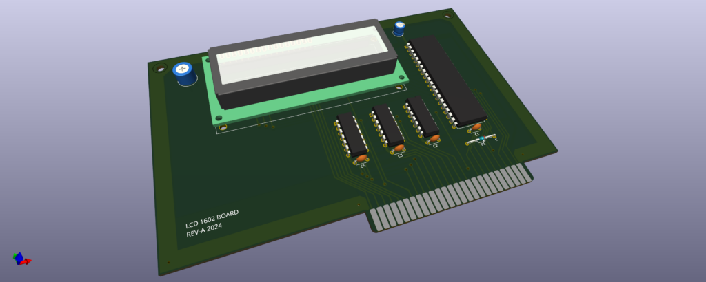
LCD Display Board

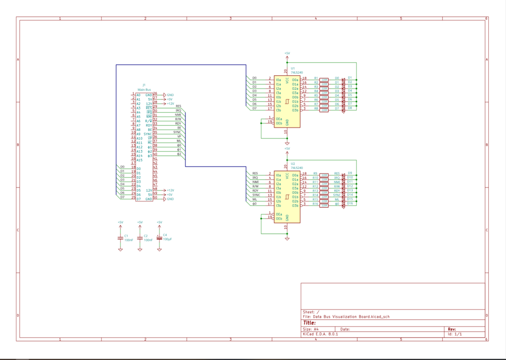
Data Bus Visualization Board
The data bus visualization board just displays the whatever value is on the data bus at the moment, together with various signals like IRQ, R/W, Clock etc. on 16 individual LEDs.

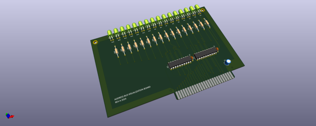
Address Bus Visualization Board
Just like the data bus visualization board, this board just shows the current content of the address bus on 16 LEDs.